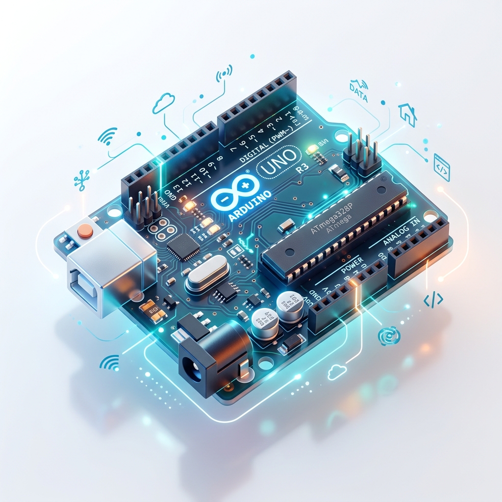
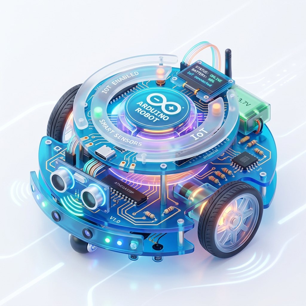
Building IoT Application
Arduino board ki basics seekhiye aur apne first smart device application banane ki shuruwat kijiye.
🔹 Introduction to Arduino
Is platform ka use electronic projects aur IoT applications banane ke liye kiya jata hai. Arduino beginners aur experts dono ke liye bahut useful hota hai kyunki iska programming environment simple aur easy hota hai.
Arduino ki madad se sensors aur modules ko connect karke unhe program kiya ja sakta hai aur real-world applications (jaise smart home, robotics) banaye ja sakte hain.
Arduino kaise kaam karta hai:
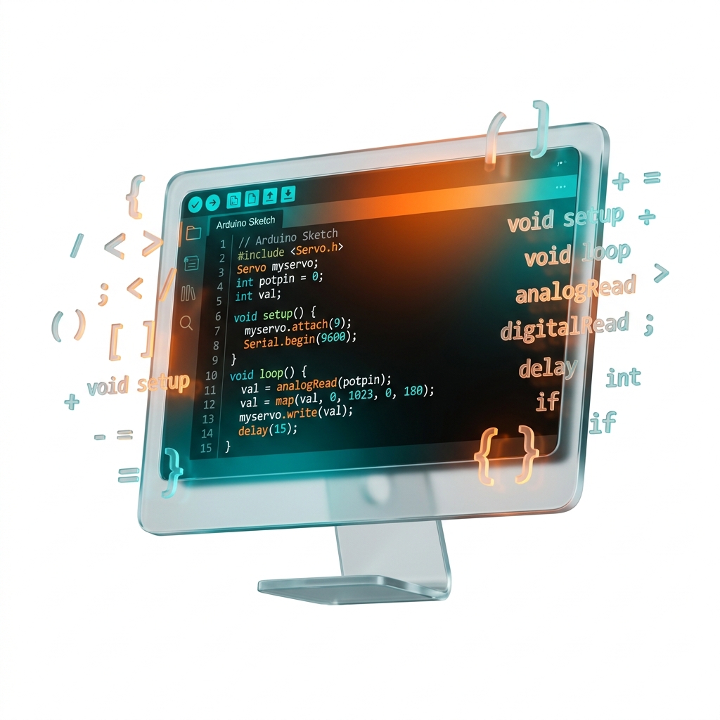
🔹 Arduino IDE
Arduino ko program karne ke liye Arduino IDE (Integrated Development Environment) ka use kiya jata hai.
Ye ek software hota hai jisme:
- 1. Code likha jata hai
- 2. Code compile hota hai (Errors check hote hain)
- 3. Code upload hota hai (Microcontroller me save hota hai)
🔹 Features of Arduino
🔹 Uses of Arduino
Arduino ka use different IoT aur automation projects me hota hai:

🔹 History of Arduino
- 1
Arduino ko 2005 me Italy me develop kiya gaya tha.
- 2
Isse Ivrea Interaction Design Institute ne students ke liye ek low-cost aur easy programming board ke roop me design kiya tha.
- 3
Arduino ek microcontroller based board hai jo ATmega series ke microcontrollers par based hota hai.
👨💻 Arduino Development Team Members:
🔴 Why Use Arduino
Arduino duniya ka sabse popular embedded aur IoT development platform mana jata hai. Iska use beginners se lekar professional developers tak sab karte hain kyunki ye easy, low-cost aur flexible platform provide karta hai.
1. Open Source Platform
Arduino ek open-source platform hai. Iska software aur hardware design publicly available hota hai.
- Arduino software free me use kar sakta hai
- Hardware design ko modify kar sakta hai
- Apna custom board bana sakta hai
Isi wajah se Arduino community bahut badi hai aur internet par iske thousands projects available hain.
2. Cross Platform Support
Arduino IDE cross-platform software hai. Ye different operating systems par chal sakta hai, yani kisi bhi computer me Arduino programming ki ja sakti hai.
3. Inexpensive (Low Cost)
Arduino boards dusre microcontroller platforms ke comparison me kaafi saste hote hain.
Original Arduino board ki cost kam hoti hai aur clone boards aur bhi low price me available hote hain. Isliye students aur beginners ke liye ye best platform mana jata hai.
4. Wide Variety of Boards
Arduino ke different types ke boards available hote hain jinko project requirement ke according select kiya ja sakta hai.
Har board me ye properties alag hoti hain. Isliye small aur large dono types ke projects me Arduino use kiya ja sakta hai.
🔴 Different Types of Arduino Board
Arduino platform me different types ke boards available hote hain jo alag-alag projects aur applications ke liye use kiye jate hain. Har board ki apni specifications, memory, pins aur features hote hain.
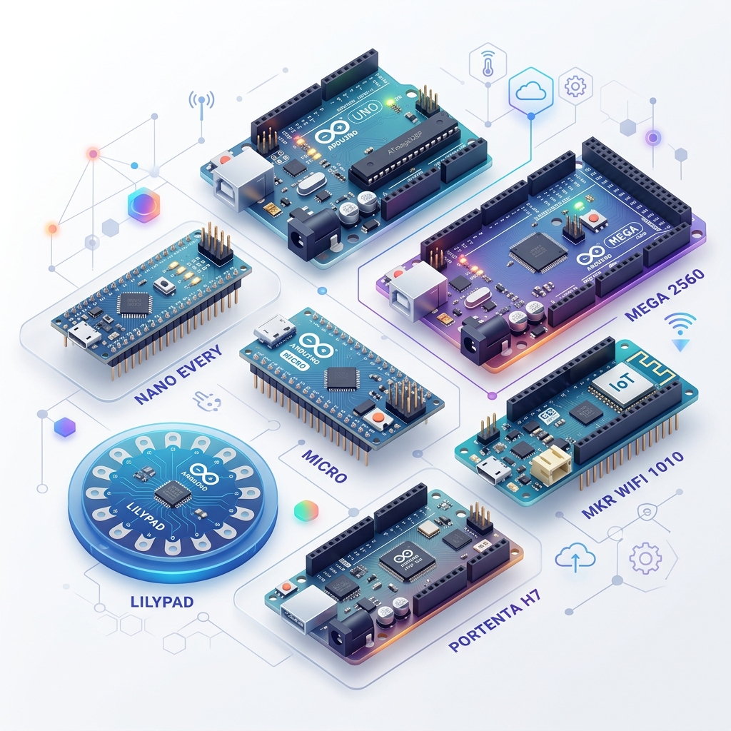
🔴 1. Arduino Uno R3
Arduino Uno sabse popular aur widely used Arduino board hai. Ye beginners aur IoT projects ke liye sabse jyada use kiya jata hai. Ye ATmega328P microcontroller par based hota hai.
⚡ Features
- Easy programming & Beginner friendly
- USB support
- Analog aur digital pins
- Sensor interfacing support
🛠️ Uses
- IoT projects & Robotics
- Automation systems
- Learning purpose
🔴 2. Arduino Nano
Arduino Nano ek small size Arduino board hota hai jo compact projects ke liye use hota hai. Ye bhi ATmega328P microcontroller par based hota hai. Iska size chhota hota hai lekin functionality Arduino Uno jaisi hoti hai.
⚡ Features
- Small size
- Breadboard friendly
- Low power consumption
🛠️ Uses
- Wearable devices
- Compact embedded systems
- Small IoT devices
🔴 3. Arduino Micro
Arduino Micro ATmega32U4 microcontroller par based hota hai. Ye USB communication ko directly support karta hai aur small-size projects ke liye suitable hota hai.
⚡ Features
- Compact design
- USB communication support
- Low power consumption
🛠️ Uses
- Keyboard projects
- Mouse controller
- Portable electronics

🔴 4. Arduino Leonardo
Arduino Leonardo bhi ATmega32U4 microcontroller par based board hai. Ye USB communication ko directly handle kar sakta hai.
⚡ Features
- USB support
- Easy interfacing
- Stable performance
🛠️ Uses
- Human interface devices
- Automation systems
🔴 5. Arduino Mega 2560 Rev 3
Arduino Mega advanced projects ke liye use hota hai. Ye ATmega2560 microcontroller par based hota hai aur isme bahut jyada pins aur memory available hoti hai.
⚡ Features
- Large memory
- More digital pins
- Multiple serial ports
🛠️ Uses
- Robotics
- 3D printers
- Large IoT projects
🔴 6. Arduino Due
Arduino Due ek high-performance board hai jo ARM Cortex microcontroller par based hota hai. Ye 32-bit architecture support karta hai aur Arduino Uno se kaafi fast hota hai.
⚡ Features
- 32-bit processing
- High speed
- Large memory support
🛠️ Uses
- Advanced automation
- Industrial systems
- Complex embedded projects
🔴 Other Important Arduino Boards
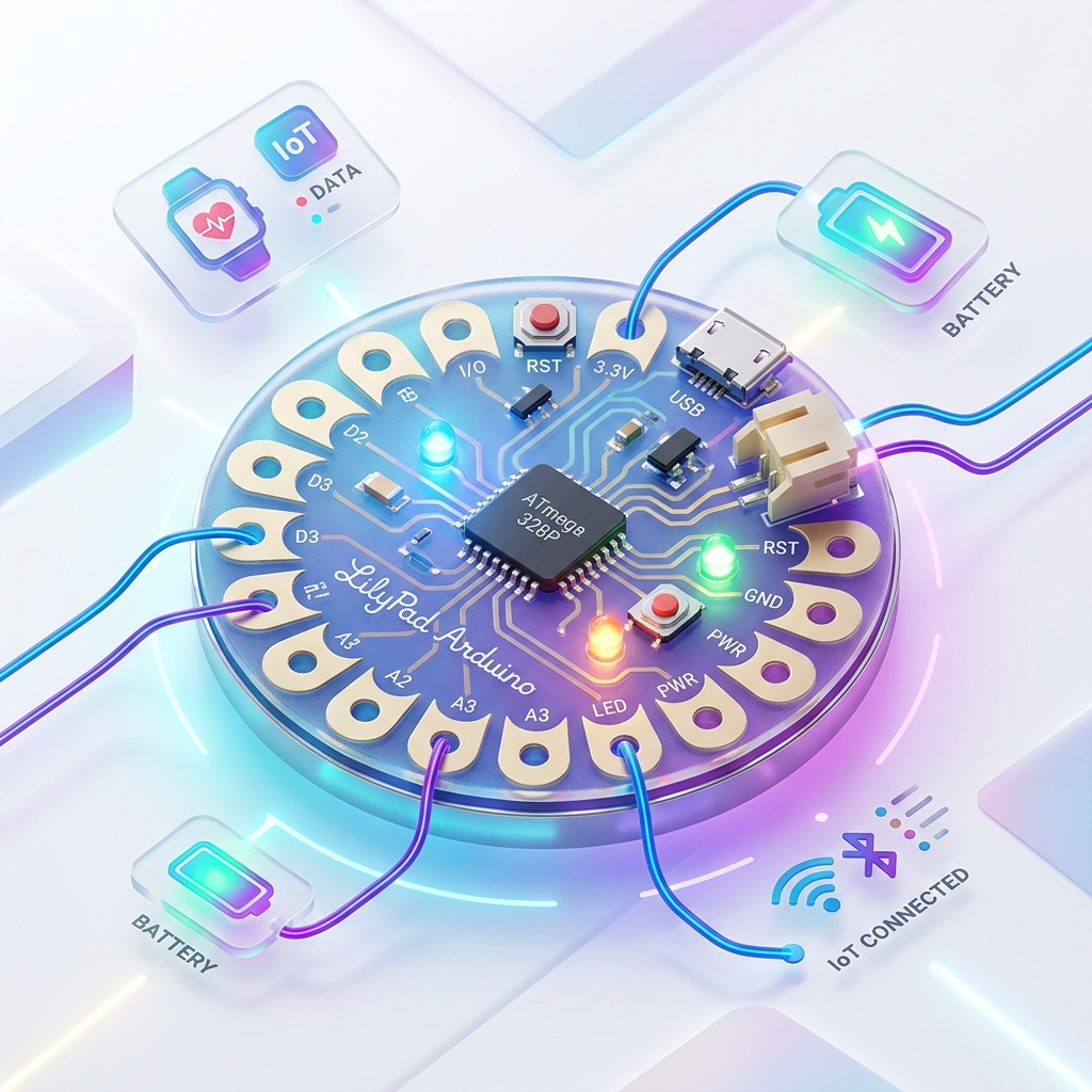
7. LilyPad Arduino
Specially wearable electronics ke liye design kiya gaya board hai.
Uses: Smart clothes, Wearables
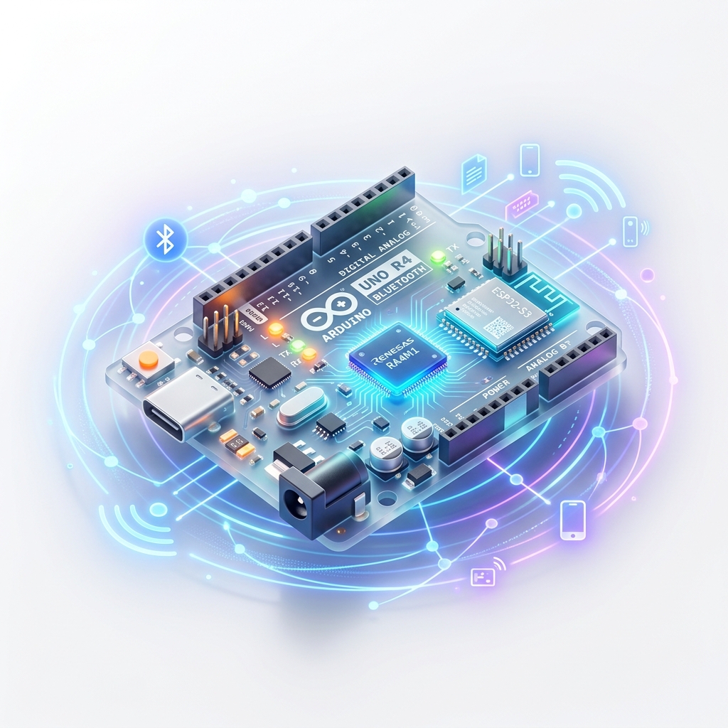
8. Arduino Bluetooth
Wireless communication support karta hai. Bluetooth module inbuilt hota hai.
Uses: Wireless control systems
9. Arduino Diecimila
Old-generation Arduino board hai jo basic embedded projects ke liye use hota tha.
10. RedBoard
Arduino Uno jaisa hi board hota hai jo compatible design provide karta hai.
11. Arduino Robot
Programmable robotic platform for robotics learning and projects.
Uses: Robotics, Automation

12. Arduino Esplora
Special board jisme inbuilt sensors aur joystick available hote hain.
Uses: Gaming projects, Sensors
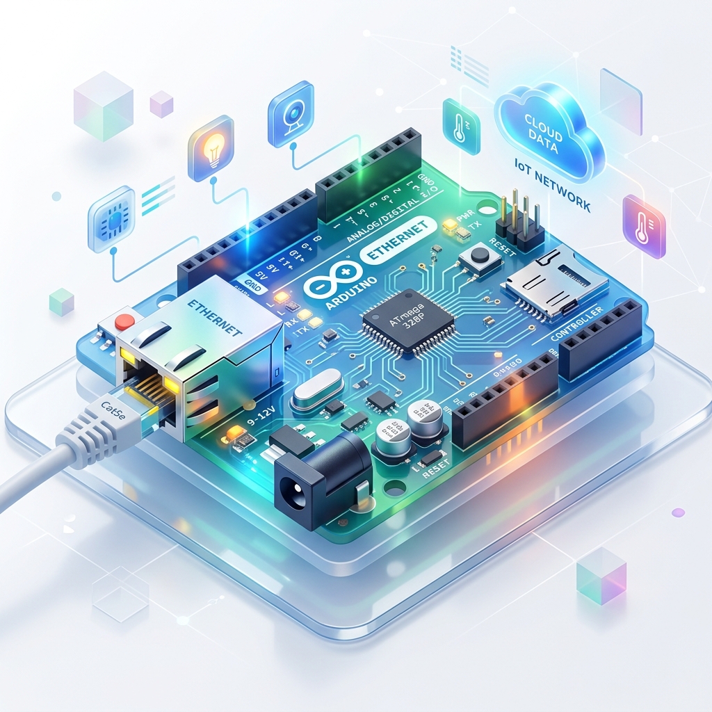
13. Arduino Ethernet
Internet communication support karta hai directly network se connect ho sakta hai.
Uses: IoT networking, Web servers
14. Arduino Zero
Modern 32-bit development board hai jo advanced embedded systems ke liye use hota hai.
Features: Fast processing, Low power
15. Arduino Pro
Lightweight aur low-power applications ke liye design kiya gaya board hai.
Uses: Portable systems, Battery-operated devices
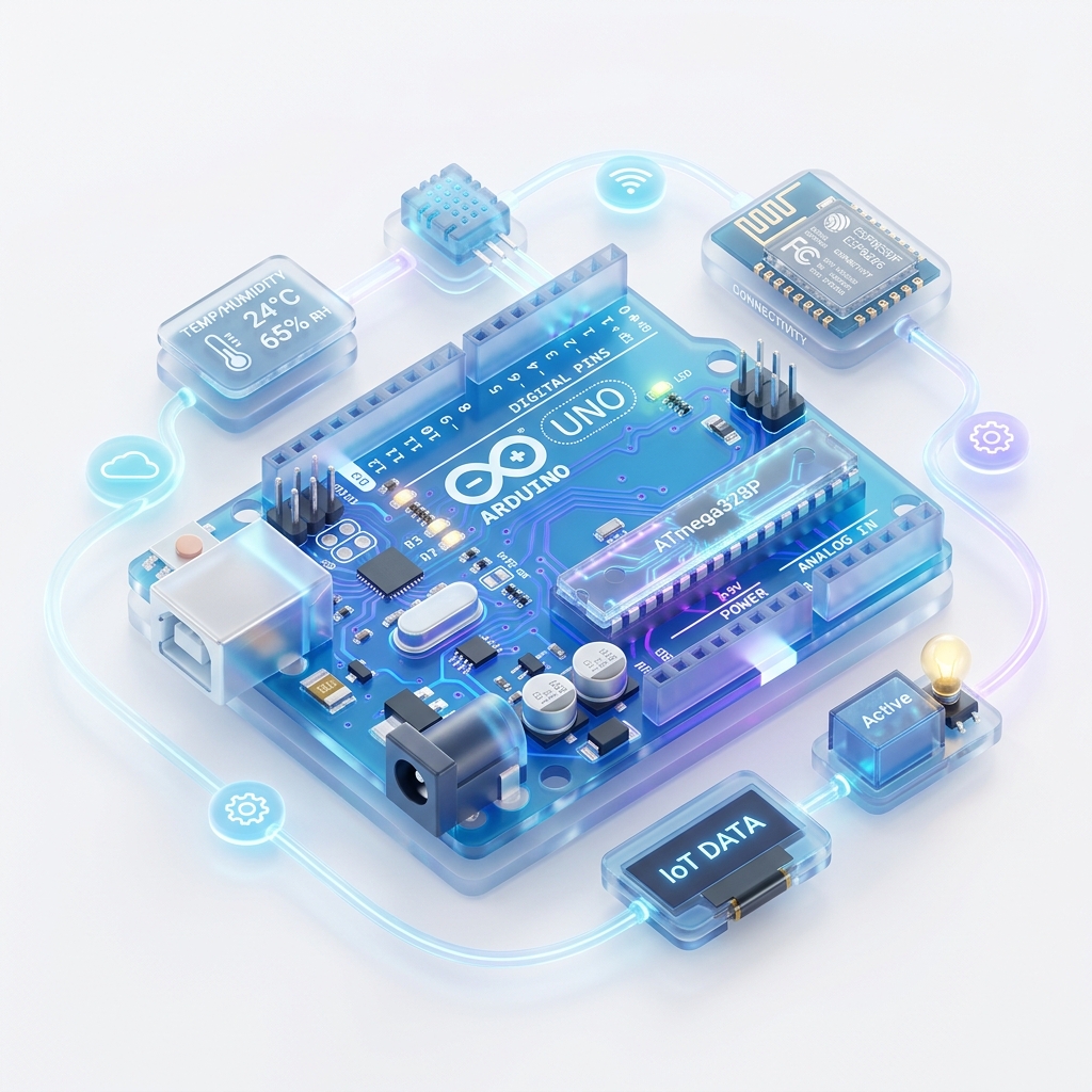
🔴 Arduino Uno R3 Deep Dive
Arduino Uno R3 duniya ka sabse popular aur sabse jyada use hone wala Arduino development board hai. Ye specially beginners, students aur IoT developers ke liye design kiya gaya hai taaki electronic projects aur embedded systems ko easily develop kiya ja sake.
Ye ATmega328P microcontroller par based hota hai aur ye sensors, motors, LEDs aur different electronic modules ko control kar sakta hai.
"R3" ka matlab hota hai "Revision 3", yani Arduino Uno ka upgraded version.
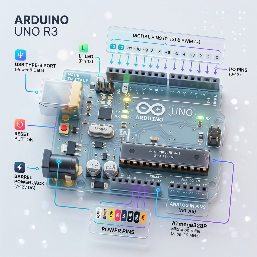
🔹 Main Components of Arduino Uno R3
1. ATmega328P Microcontroller
Ye Arduino Uno ka main brain hota hai. Iske andar CPU, RAM, ROM, Timers aur Input/Output ports available hote hain. Ye program instructions ko execute karta hai aur poore board ko control karta hai.
2. USB Port
USB port ka use Computer se connection, Program upload aur Power supply ke liye hota hai. USB cable ke through Arduino ko directly laptop ya PC se connect kiya jata hai.
3. DC Power Jack
Agar USB available na ho to external adapter ya battery se Arduino ko power di ja sakti hai. Usually 7V se 12V tak supply di jati hai.
4. Reset Button
Reset button board par uploaded program ko dobara start karta hai. Is button ko press karte hi Arduino fir se beginning se code execute karta hai.
5. Crystal Oscillator & Voltage Regulator
Crystal Oscillator: 16 MHz ka hota hai, ye clock signals generate karta hai jisse microcontroller ki processing speed control hoti hai.Voltage Regulator: Incoming voltage ko stable banata hai taaki board safe rahe aur proper voltage receive kare.
🔴 Technical Specifications
| Feature | Details |
|---|---|
| Microcontroller | ATmega328P |
| Operating Voltage | 5V |
| Input Voltage | 7V – 12V |
| Digital I/O Pins | 14 (including 6 PWM pins) |
| Analog Input Pins | 6 (A0 - A5) |
| Flash Memory | 32 KB |
| SRAM & EEPROM | 2 KB (SRAM) | 1 KB (EEPROM) |
| Clock Speed | 16 MHz |
| USB Connection | USB Type-B |
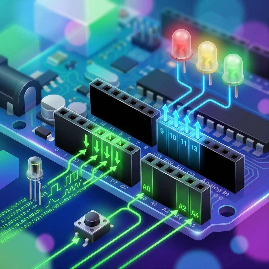
🔴 Pins of Arduino Uno R3
1. Digital Pins (0–13)
Total 14 digital pins (0-13) hoti hain jo Input ya Output mode dono me kaam kar sakti hain. Input mode me sensor data read karti hain aur Output mode me LED, motor aadi control karti hain.
2. PWM Pins (3, 5, 6, 9, 10, 11)
PWM (Pulse Width Modulation) pins analog-like output generate karti hain. Inka use LED brightness control, motor speed control, aur servo control me hota hai.
3. Analog Pins (A0–A5)
Total 6 analog input pins hoti hain jo analog signals ko read karti hain (jaise Temperature sensor, LDR, Gas sensor, Potentiometer). Arduino ka ADC (Analog to Digital Converter) is signal ko digital value (0–1023) me convert karta hai.
4. Power Pins & Communication Protocols
⚡ Power Pins
- VIN: External voltage input
- 5V / 3.3V: Output voltages for sensors
- GND: Ground (0V)
- RESET: Reset pin
📡 Communication Protocols
- UART: Serial Communication (RX, TX)
- SPI: Fast Communication (Pins 10,11,12,13)
- I2C: 2-wire Protocol (SDA: A4, SCL: A5)
Memory Storage
- Flash Memory (32 KB)Program code store karne ke liye use hoti hai.
- SRAM (2 KB)Temporary data storage ke liye use hoti hai.
- EEPROM (1 KB)Permanent data storage ke liye use hoti hai.
Final Understanding
Arduino Uno R3 ek complete development board hai jo sensors read karta hai, data process karta hai aur output devices ko control karta hai. Isme ATmega328P microcontroller, Digital pins, Analog pins, PWM support aur Communication protocols sab available hote hain.
🔥 Top Applications:
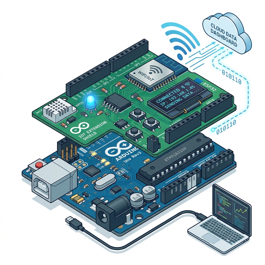
🔴 Arduino Shield
Shield ki madad se Arduino me naye features aur capabilities add ki jati hain bina extra complex wiring ke. Ye directly Arduino Uno ya doosre compatible boards ke pins par connect hota hai.
Ye board Power pins, Communication pins aur Digital/Analog pins ka use karke additional functions perform karta hai.
⚡ Features of Arduino Shield
- Easy installation
- Plug and play support
- Additional functionality
- Sensor aur module support
- Fast development
✅ Advantages
- Wiring complexity kam hoti hai
- Development fast hota hai
- Multiple features easily add kiye ja sakte hain
- Beginners ke liye easy hota hai
Types of Arduino Shields
1. Ethernet Shield
Internet aur network communication ke liye use hota hai.
Uses: IoT networking, Web server projects
2. Motor Shield
Motors ko control karne ke liye use hota hai.
Uses: Robotics, Automation systems
3. WiFi Shield
Arduino ko wireless internet se connect karne ke liye use hota hai.
Uses: Smart home systems, IoT communication
4. GSM Shield
Mobile network communication provide karta hai.
Uses: SMS sending, Remote monitoring
5. Bluetooth Shield
Bluetooth communication ke liye use hota hai.
Uses: Wireless control system, Mobile connectivity
🔹 Introduction to Arduino IDE
Arduino IDE (Integrated Development Environment) ek software platform hai jiska use Arduino board ko program karne ke liye kiya jata hai. Ye software user ko code likhne, compile karne aur Arduino board me upload karne ki facility provide karta hai. Arduino IDE ka interface simple aur user-friendly hota hai jiski wajah se beginners bhi easily programming kar sakte hain.
Main Components / Menus of Arduino IDE
🔴 1. File Menu
File menu ka use files aur projects ko manage karne ke liye kiya jata hai. Is menu me new sketch create karna, old sketch open karna aur files save karna jaise options available hote hain.
New (Ctrl + N)
Naya sketch/program create karne ke liye use hota hai.
Open (Ctrl + O)
Pehle se saved Arduino sketch ko open karne ke liye use hota hai.
Save (Ctrl + S)
Current sketch ko save karne ke liye use hota hai.
Save As
Existing file ko naye naam se save karne ke liye use hota hai.
Examples
Arduino IDE me already available sample programs (Blink LED) ko open karne ke liye.
Preferences
IDE settings change karne ke liye use hota hai (Theme, Font size).
🔴 2. Edit Menu
Edit menu ka use code editing ke liye hota hai. Is menu me text editing aur code formatting ke options available hote hain.
🔴 3. Sketch Menu
Sketch menu program compiling aur library management ke liye use hota hai.
- Verify / Compile (Ctrl + R): Program me errors check karta hai aur code ko compile karta hai.
- Upload (Ctrl + U): Compiled code ko Arduino board me upload karta hai.
- Include Library: External libraries ko add karne ke liye use hota hai. Libraries sensors aur modules ko easily use karne me help karti hain.
🔴 4. Tools Menu
- Board: Arduino board select karne ke liye (e.g., Uno, Mega, Nano).
- Port: COM port select karne ke liye jahan Arduino connected hota hai.
- Programmer: Programming method select karne ke liye.
- Serial Monitor (Ctrl + Shift + M): Arduino aur computer ke beech serial communication display karta hai.
🔴 5. Help Menu
- Documentation access
- Troubleshooting
- Reference material
- Software information
Toolbar
Quick-access buttons (Verify, Upload, New, Open, Save, Serial Monitor).
Text Editor Area
Main coding area jahan variables, functions, logic likhe jate hain.
Message & Console
Errors, warnings, successful messages aur compilation process show karta hai.
Status Bar
Selected board, COM port, aur IDE status show karta hai.
🔴 Arduino Library
Arduino library ek pre-written code collection hoti hai jo programming ko easy banati hai. Library me already functions aur commands available hote hain jinki help se sensors, displays, motors aur modules ko easily control kiya ja sakta hai.
Arduino libraries programmer ka time bachati hain aur complex coding ko simple bana deti hain.

⚡ Working of Arduino Library
Jab kisi sensor ya module ko Arduino ke saath use karna hota hai to uske liye related library include ki jati hai. Library include karne ke baad:
- Ready-made functions available ho jate hain
- Hardware ko easily control kiya ja sakta hai
✅ Advantages of Arduino Library
- Coding easy ho jati hai
- Time saving hota hai
- Errors kam hote hain
- Complex devices ko easily use kiya ja sakta hai
📌 Examples of Arduino Libraries
| Library | Use |
|---|---|
| Servo Library | Servo motor control |
| LiquidCrystal | LCD display control |
| WiFi Library | WiFi communication |
| EEPROM Library | EEPROM memory access |
🛠️ How to Include Library
Arduino IDE me library include karne ke liye:
Sketch → Include Library🔴 Making Input and Output Pin
Arduino me pins ko input ya output mode me configure kiya jata hai. Pin mode decide karta hai ki pin data receive karegi ya data send karegi.
📥 Input Pin
Input pin external devices se data receive karti hai.
👉 Examples:
- Sensor input
- Push button input
⚡ Working:
Input mode me Arduino voltage signal ko read karta hai aur HIGH ya LOW value detect karta hai.
📤 Output Pin
Output pin external devices ko signal bhejti hai.
👉 Examples:
- LED control
- Motor control
- Buzzer control
⚡ Working:
Output mode me Arduino HIGH (5V) ya LOW (0V) signal provide karta hai.
📌 pinMode() Function
Arduino me pins ko configure karne ke liye pinMode() function use hota hai.
// Syntax
// Examples
🔴 How to Select the Board
Arduino IDE me program upload karne se pehle correct Arduino board select karna bahut important hota hai. Agar wrong board select ho jaye to code upload nahi hoga ya errors aa sakte hain.
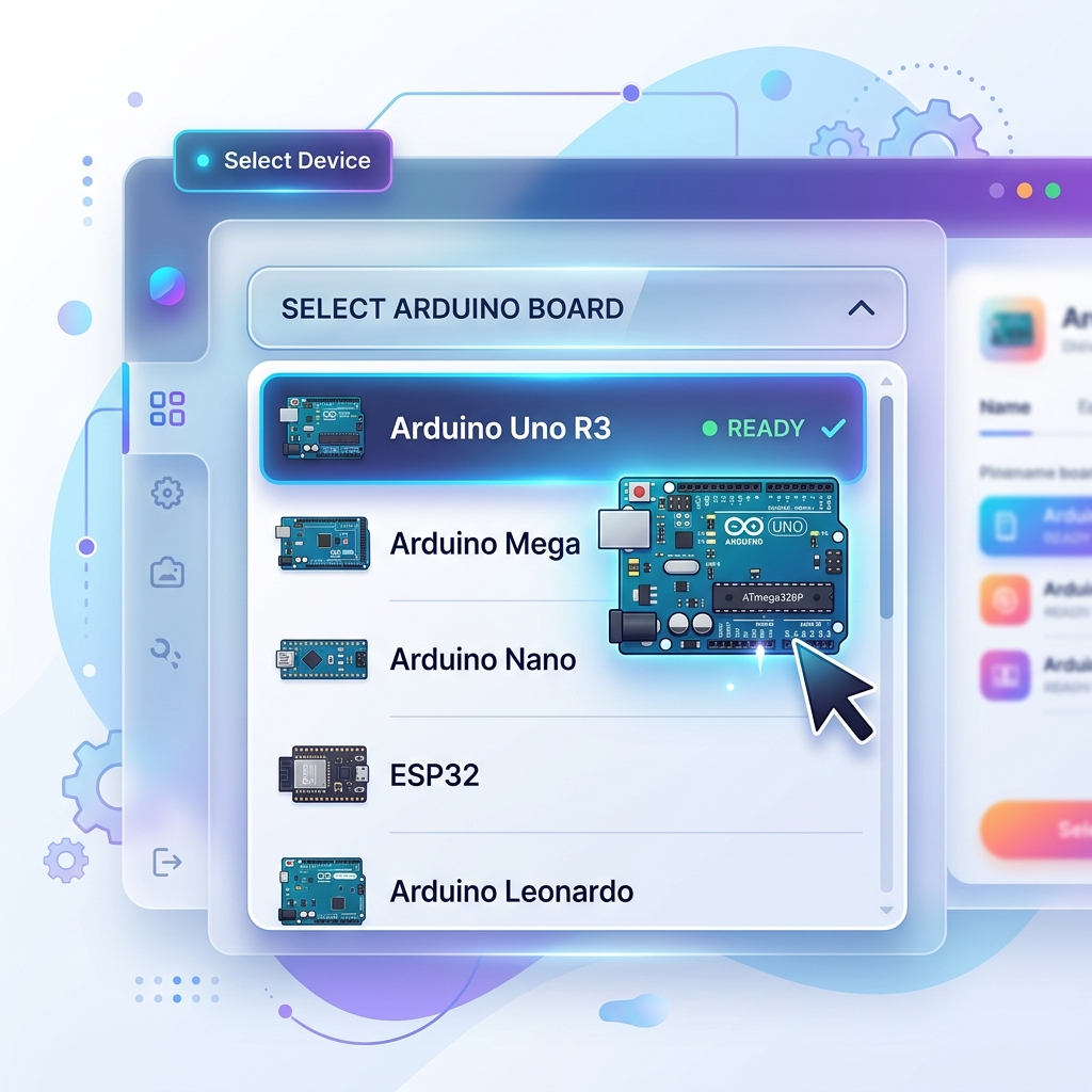
🛠️ Steps to Select Board
- 1Arduino IDE open kare
- 2Menu bar me:
Tools → Boardselect kare - 3Required board choose kare
👉 Example: Arduino Uno, Arduino Mega, Arduino Nano
❓ Why Board Selection Important
Board selection se IDE ko pata chalta hai:
- Kaunsa microcontroller use ho raha hai
- Kitni memory available hai
- Kaunsi upload settings use hongi
🔴 Writing and Editing Codes in Sketch
Arduino IDE me code text editor area me likha aur edit kiya jata hai.

Writing Code
User variables declare karta hai, functions likhta hai, aur logic create karta hai.
Editing Code
Code ko modify karne ke liye Copy, Paste, Undo, aur Redo jaise editing options available hote hain.
Verify / Compile
Code likhne ke baad Verify button press karke errors check kiye jate hain.
Uploading Code
Compile successful hone ke baad Upload button se program Arduino board me upload kiya jata hai.
🔴 Arduino Sketch Structure
Arduino program mainly do important functions par based hota hai:
setup()loop()
// Basic Structure of Arduino Sketch

setup() Function
Ye function sirf ek baar execute hota hai jab Arduino start hota hai ya Reset hota hai.
⚡ Uses:
- Pin mode define karna
- Serial communication start karna
- Initial settings configure karna
loop() Function
Ye function continuously repeat hota rehta hai jab tak Arduino ON rehta hai. Isme main logic aur repeated tasks likhe jate hain.
⚡ Uses:
- LED blinking
- Sensor reading
- Motor control
🔴 What is Function
Program me jab same task ko baar-baar perform karna ho to function ka use kiya jata hai. Isse code reusable aur easy ho jata hai.
👉 "Function = instructions ka group jo ek specific kaam karta hai"
🔹 Features / Points of Function
1 Reusability
Ek function ko baar-baar call kiya ja sakta hai. Isse same code ko repeatedly likhne ki zarurat nahi padti.
2 Modularity
Function program ko small-small parts me divide karta hai. Isse program samajhna aur manage karna easy ho jata hai.
3 Reduces Complexity
Large program ko simple aur organized banata hai. Program ki readability improve hoti hai.
4 Easy Debugging
Agar error aaye to specific function ko check karke error easily find kiya ja sakta hai.
🔴 Embedded C Language
Ye C language ka extended version hota hai jisme hardware control aur low-level programming features available hote hain.
👉 Embedded C ka use kahan hota hai?
Arduino
Microcontroller
Robotics
IoT Systems
🔹 Features of Embedded C
Fast Execution
Code bahut tezi se execute hota hai
Hardware Control
Direct hardware ko control kar sakte hain
Low Memory Usage
Kam memory mein bhi chalta hai
Real-time Support
Real-time programming possible hai
Portable Language
Different platforms par chal sakta hai
🔴 Variables
Program execution ke dauran variable ki value change ho sakti hai.
👉 "Variable = data store karne ka naam"
🔹 Example
a → Variable hai
10 → Stored value hai
🔴 Rules for Variable Naming
🔸 1. Variable Name Alphabet ya Underscore se Start Hona Chahiye
✅ Correct
temp, _value❌ Wrong
1temp🔸 2. Space Allowed Nahi Hota
✅ Correct
totalMarks❌ Wrong
total marks🔸 3. Special Characters Allowed Nahi Hote
Special symbols jaise @ # % & use nahi kar sakte.
🔸 4. Keywords Use Nahi Kar Sakte
C language ke reserved keywords variable names nahi ban sakte.
🔸 5. Variable Name Meaningful Hona Chahiye
✅ Correct
studentAge❌ Wrong
x🔸 6. Variable Case Sensitive Hota Hai
Dono different variables hote hain.
🔸 7. Numbers Use Kar Sakte Hain But Starting Me Nahi
✅ Correct
mark1❌ Wrong
1mark🔸 8. Variable Length Limited Hoti Hai
Variable ka naam bahut jyada long nahi hona chahiye aur readable hona chahiye.
🔴 Data Types
Different data types alag-alag memory size aur value range support karte hain.
🔹 Common Data Types in Embedded C
| Data Type | Use |
|---|---|
| int | Integer values |
| float | Decimal values |
| char | Single character |
| double | Large decimal values |
| void | No value |
| long | Large integer values |
| short | Small integer values |
| unsigned int | Positive integers only |
🔹 Data Types — Detail
🔹 int — Integer
Integer numbers store karta hai.
🔹 float — Decimal
Decimal numbers store karta hai.
🔹 char — Character
Single character store karta hai.
🔹 double — Large Decimal
Large decimal precision values store karta hai. Float se zyada accurate hota hai.
🔹 void — No Value
Jab koi value return nahi hoti tab use hota hai. Jaise void setup()
🔴 Operators in Embedded C
👉 "Operators = calculations aur logical operations karne wale symbols"
Embedded C language me operators ka use Calculation, Comparison, Decision making, aur Logical checking ke liye kiya jata hai.
🔹 Types of Operators
1. Arithmetic Operators
Arithmetic operators mathematical calculations (add, subtract, etc.) perform karne ke liye use hote hain.
| Operator | Work |
|---|---|
| + | Addition |
| - | Subtraction |
| * | Multiplication |
| / | Division |
| % | Modulus (Remainder) |
2. Relational Operators
Ye operators do values ko compare karte hain (jaise temperature limit check karna). Ye TRUE (1) ya FALSE (0) result dete hain.
| Operator | Meaning |
|---|---|
| == | Equal to |
| != | Not equal to |
| > | Greater than |
| < | Less than |
| >= | Greater than equal to |
| <= | Less than equal to |
3. Logical Operators
Jab ek se zyada conditions ko combine karna ho (e.g. agar raat hai AUR motion detect hua hai, tabhi light on karo).
| Operator | Meaning |
|---|---|
| && | Logical AND (Dono true honge tabhi TRUE) |
| || | Logical OR (Koi ek bhi true to TRUE) |
| ! | Logical NOT (Condition ka opposite karta hai) |
4. Assignment Operators
Ye variables me direct value store karne ke liye use hote hain. Short calculations ke liye += aur -= zyada use hote hain.
| Operator | Meaning |
|---|---|
| = | Assign value (e.g. x = 5) |
| += | Add & assign (x += 5 means x = x + 5) |
| -= | Subtract & assign (x -= 5 means x = x - 5) |
| *= | Multiply & assign |
| /= | Divide & assign |
5. Increment and Decrement
Kisi sensor ke counter ko 1 step aage (Increase) ya 1 step piche (Decrease) karne ke liye inka use hota hai.
6. Bitwise Operators
Ye Arduino ke pin level (0 aur 1) par kaam karne ke liye (hardware registers control karne ke liye) sabse important hote hain.
| Operator | Meaning |
|---|---|
| & | Bitwise AND |
| | | Bitwise OR |
| ^ | Bitwise XOR |
| ~ | Bitwise NOT |
| << | Left Shift (Bits ko left khiskata hai) |
| >> | Right Shift (Bits ko right khiskata hai) |
7. Conditional (Ternary) Operator
Ye if-else statement ka short form hota hai. Isse ek hi line me decision ho jata hai.
🔴 Operator Precedence
Jab ek expression me bahut saare operators use hote hain to execution kis order me hoga, usko operator precedence kehte hain.
🔴 Conditional Statements
In statements ki help se program kisi condition ko check karta hai aur uske according different instructions execute karta hai.
👉 Simple words me: "Condition TRUE ya FALSE hone par alag-alag code execute karna"
Embedded C aur Arduino programming me conditional statements bahut important hote hain kyunki inki help se sensors aur devices ke according automatic decisions liye ja sakte hain.
🔹 Types of Conditional Statements
1. if
Statement
2. if-else
Statement
3. else-if
Ladder
🔴 1. if Statement
if statement ka use tab kiya jata hai jab kisi condition ke TRUE hone par hi code execute karna ho. Agar condition FALSE ho jaye to program if block ko skip kar deta hai.
⚡ Working:
- Program condition check karta hai
- Agar condition TRUE ho: if block execute hota hai
- Agar condition FALSE ho: if block execute nahi hota
a > 5 TRUE hai isliye message print hoga.🔴 2. if-else Statement
if-else statement ka use tab kiya jata hai jab: Ek condition TRUE hone par ek block execute ho aur FALSE hone par doosra block execute ho.
⚡ Working:
- Condition check hoti hai
- Agar TRUE: if block execute hota hai
- Agar FALSE: else block execute hota hai
else block execute hoga.🔴 3. else-if Ladder
else-if ladder ka use multiple conditions check karne ke liye kiya jata hai. Jab program me ek se jyada conditions ho aur har condition ke according alag action perform karna ho tab else-if ladder use hota hai.
⚡ Working:
- Pehli condition check hoti hai
- Agar TRUE: Us block ka code execute hota hai
- Agar FALSE: Next condition check hoti hai
- Ye process tab tak chalta hai jab tak koi condition TRUE na ho jaye
- Agar koi bhi condition TRUE na ho: else block execute hota hai
marks >= 70 TRUE hai isliye Grade B print hoga.🔴 Loop Statements
Jab program me same instructions ko repeatedly chalana ho tab loops use kiye jate hain.
👉 Simple words me: "Loop = same code ko repeat karna"
Loops programming ko easy aur short banate hain kyunki baar-baar same code likhne ki zarurat nahi padti.
🔹 Types of Loops
1. while
Loop
2. do-while
Loop
3. for
Loop
🔴 1. while Loop
while loop ek entry-controlled loop hota hai. Isme condition pehle check hoti hai aur agar condition TRUE hoti hai tabhi loop execute hota hai. Agar condition starting me hi FALSE ho to loop ek baar bhi execute nahi hota.
⚡ Working:
- Condition check hoti hai
- Agar TRUE: Loop body execute hoti hai
- Fir condition dobara check hoti hai
- Jab tak condition TRUE rahegi loop chalta rahega
1
2
3
4
5
🔴 2. do-while Loop
do-while loop ek exit-controlled loop hota hai. Isme condition baad me check hoti hai, isliye ye loop kam se kam ek baar zarur execute hota hai chahe condition FALSE hi kyon na ho.
⚡ Working:
- Pehle loop body execute hoti hai
- Fir condition check hoti hai
- Agar condition TRUE ho: Loop repeat hota hai
- Agar FALSE ho: Loop stop ho jata hai
1
2
3
4
5
🔴 3. for Loop
for loop ka use tab kiya jata hai jab repetitions ki exact quantity pehle se known ho. Ye sabse commonly used loop hai. Isme initialization, condition, aur increment/decrement ek hi line me likhe jate hain.
⚡ Working:
- Initialization execute hota hai
- Condition check hoti hai
- Agar TRUE: Loop body execute hoti hai
- Increment/Decrement hota hai
- Fir condition dobara check hoti hai
1
2
3
4
5
🔴 Infinite Loop
Agar loop ki condition kabhi FALSE na ho to loop continuously chalta rehta hai. Isse infinite loop kehte hain.
| Loop | Condition Check | Execution |
|---|---|---|
| while | Starting me | 0 ya more times |
| do-while | End me | At least 1 time |
| for | Starting me | Fixed repetitions |
🔴 Inbuilt Functions for Digital Input/Output
Arduino me kai inbuilt functions available hote hain jo digital input aur output devices ko control karne ke liye use kiye jate hain. In functions ki madad se programmer bina complex coding ke hardware ko control kar sakta hai.
🔴 1. pinMode()
pinMode() function kisi pin ko INPUT ya OUTPUT mode me configure karne ke liye use hota hai. Jab bhi kisi pin ko use karna ho to sabse pehle uska mode define karna zaruri hota hai.
⚡ Parameters & Uses:
- pin → Pin number
- mode → INPUT, OUTPUT ya INPUT_PULLUP
- Uses: LED control, Push button input, Sensor interfacing
🔴 2. digitalWrite()
digitalWrite() function digital pin par HIGH ya LOW value bhejne ke liye use hota hai. Ye output devices jaise LED, buzzer aur relay ko control karne ke liye use hota hai.
⚡ Working & Uses:
- HIGH = 5 Volt Output
- LOW = 0 Volt Output
- Uses: LED ON/OFF, Relay control, Buzzer control
🔴 3. digitalRead()
digitalRead() function digital input pin ki value read karne ke liye use hota hai. Ye function HIGH ya LOW value return karta hai.
⚡ Working & Uses:
- Agar signal present ho: HIGH
- Agar signal present na ho: LOW
- Uses: Push button reading, Digital sensors, Switch monitoring
🔴 4. shiftIn()
shiftIn() function serial data ko bit-by-bit read karne ke liye use hota hai. Ye external devices se serial data receive karta hai aur usse byte me convert karta hai.
⚡ Parameters & Uses:
- bitOrder → MSBFIRST ya LSBFIRST
- Uses: Shift registers, Serial communication, Sensor modules
🔴 5. shiftOut()
shiftOut() function serial form me data ko bit-by-bit transmit karne ke liye use hota hai. Ye Arduino se external devices ko serial data bhejta hai.
⚡ Parameters & Uses:
- value → Send ki jane wali value
- Uses: LED matrix, Shift register control, Serial devices
🔴 6. tone() & noTone()
tone() function buzzer ya speaker par specified frequency ki sound generate karta hai, aur noTone() us sound ko stop karne ke liye use hota hai.
⚡ Parameters & Uses:
- frequency → Sound frequency (Hz)
- duration → Time in milliseconds (optional)
- Uses: Alarm system, Buzzer notification, Sound generation
| Function | Work |
|---|---|
| pinMode() | Pin mode set karta hai (INPUT/OUTPUT) |
| digitalWrite() | HIGH/LOW output bhejta hai |
| digitalRead() | Digital input read karta hai |
| shiftIn() | Serial data receive karta hai |
| shiftOut() | Serial data send karta hai |
| tone() | Sound generate karta hai |
| noTone() | Sound stop karta hai |
🔴 Inbuilt Functions for Analog Input and Output
Arduino me analog signals ko read aur generate karne ke liye kuch special inbuilt functions use kiye jate hain. Analog signals continuously change hote hain, isliye unhe process karne ke liye Arduino ke ADC (Analog to Digital Converter) aur PWM techniques ka use kiya jata hai.
🔴 1. analogRead()
analogRead() function analog input pins se analog voltage ko read karne ke liye use hota hai. Arduino Uno me 6 analog input pins hoti hain: A0, A1, A2, A3, A4, A5. Ye function analog signal ko digital value me convert karke return karta hai.
⚡ Return Value & Uses:
- ADC 10-bit ka hota hai (Range: 0 to 1023)
- 0V → 0, 2.5V → 512, 5V → 1023
- Uses: LDR sensor, Temperature sensor, Potentiometer, Gas sensor
🔴 2. analogWrite()
analogWrite() function PWM (Pulse Width Modulation) signal generate karne ke liye use hota hai. Arduino Uno actual analog voltage generate nahi karta, balki PWM signal generate karta hai jo analog output jaisa behavior deta hai.
⚡ Values & Uses:
- PWM Pins: 3, 5, 6, 9, 10, 11
- Value Range: 0 se 255 tak
- 0 = OFF, 127 = 50% Output, 255 = Fully ON
- Uses: LED brightness, Motor speed, Servo control
🔴 analogReference()
analogReference() function ADC ke reference voltage ko select karne ke liye use hota hai. Reference voltage decide karti hai ki Arduino analog input ko kis voltage range ke according measure karega.
1. DEFAULT
DEFAULT reference me Arduino apni supply voltage (Uno me 5V) ko reference ke roop me use karta hai.
// ADC: 0V → 0 | 5V → 1023
2. INTERNAL
INTERNAL reference Arduino ke internal voltage source ko use karta hai (Uno me 1.1 Volt). Small voltage measurements me accuracy increase hoti hai.
// ADC: 0V → 0 | 1.1V → 1023
3. INTERNAL1V1
Ye specifically 1.1V internal reference ko select karta hai. (Precision sensors, Low voltage measurement).
4. INTERNAL2V56
Kuch Arduino boards me 2.56V internal reference available hota hai. (Medium voltage applications).
5. EXTERNAL
EXTERNAL mode me user khud AREF pin par external reference voltage provide karta hai. Custom voltage range aur precision measurements ke liye use hota hai.
// Example if AREF = 3.3V: 0V → 0 | 3.3V → 1023
| Function | Work |
|---|---|
| analogRead() | Analog input read karta hai |
| analogWrite() | PWM output generate karta hai |
| DEFAULT | 5V reference |
| INTERNAL | Internal reference voltage (1.1V for Uno) |
| INTERNAL1V1 | 1.1V reference |
| INTERNAL2V56 | 2.56V reference |
| EXTERNAL | External reference voltage (via AREF pin) |
🔴 Inbuilt Functions for Time
Arduino me time-related operations perform karne ke liye kuch important inbuilt functions available hote hain. In functions ka use delay create karne, execution time measure karne aur timing control karne ke liye kiya jata hai. Ye functions LEDs blinking, sensor timing, motor control aur automation projects me bahut useful hote hain.
🔴 1. delay()
delay() function program execution ko specified milliseconds ke liye stop kar deta hai. Jab delay function execute hota hai to Arduino us duration tak next instruction execute nahi karta.
⚡ Working & Uses:
- 1000 ms = 1 Second
- 500 ms = 0.5 Second
- LED 1 second ON rahegi fir next instruction chalega.
- Uses: LED blinking, Traffic light control, Alarm systems
🔴 2. delayMicroseconds()
delayMicroseconds() function microsecond level ka delay generate karta hai. Ye bahut small timing requirements ke liye use hota hai.
⚡ Relations & Uses:
- 1000 Microseconds = 1 Millisecond
- 1000000 Microseconds = 1 Second
- Uses: Pulse generation, Ultrasonic sensor timing, High-speed switching
🔴 3. millis()
millis() function Arduino start hone ke baad se kitne milliseconds beet chuke hain wo return karta hai. Ye function timer ki tarah kaam karta hai.
⚡ Return Type & Uses:
- Return Type: unsigned long
- Agar Arduino 5 second se chal raha hai, to 5000 return karega.
- Uses: Time measurement, Non-blocking delay
🔴 4. micros()
micros() function Arduino start hone ke baad se kitne microseconds beet chuke hain wo return karta hai. Ye millis() se bhi jyada accurate timing provide karta hai.
⚡ Return Type & Uses:
- Return Type: unsigned long
- Agar 250 microseconds beet chuke hain, to 250 return karega.
- Uses: High-speed timing, Pulse width measurement
| Feature | millis() | micros() |
|---|---|---|
| Unit | Milliseconds | Microseconds |
| Accuracy | Lower | Higher |
| Measurement | Normal timing | Very precise timing |
| Common Use | General projects | High-speed applications |
| Function | Work |
|---|---|
| delay() | Milliseconds delay |
| delayMicroseconds() | Microseconds delay |
| millis() | Arduino start se milliseconds count |
| micros() | Arduino start se microseconds count |
🔴 Inbuilt Functions of Math
Arduino aur Embedded C me mathematical calculations ko easy banane ke liye kai inbuilt math functions available hote hain. In functions ki madad se programmer bina complex formulas likhe calculations perform kar sakta hai. Ye functions scientific calculations, sensor data processing aur engineering applications me bahut useful hote hain.
🔴 1. abs()
abs() function kisi number ki absolute value return karta hai (number ka positive value).
🛠️ Uses:
Distance calculation, Error calculation, Sensor value comparison
🔴 2. max()
max() function do values me se badi value return karta hai.
🛠️ Uses:
Maximum sensor value finding, Comparison operations
🔴 3. min()
min() function do values me se chhoti value return karta hai.
🛠️ Uses:
Minimum value detection, Range checking
🔴 4. pow()
pow() function kisi number ki power calculate karta hai.
🛠️ Uses:
Mathematical calculations, Scientific formulas
🔴 5. sqrt()
sqrt() function kisi number ka square root calculate karta hai.
🛠️ Uses:
Engineering calculations, Distance measurement, Mathematical operations
| Function | Work |
|---|---|
| abs() | Absolute value |
| max() | Maximum value |
| min() | Minimum value |
| pow() | Power calculation |
| sqrt() | Square root |
🔴 Inbuilt Functions for Characters
Character handling functions characters ko identify aur verify karne ke liye use kiye jate hain. Ye functions text processing, password checking aur input validation me bahut useful hote hain.
🔴 1. isAlpha()
Check karta hai ki character alphabet hai ya nahi.
🔴 2. isAlphaNumeric()
Check karta hai ki character alphabet ya number hai ya nahi.
🔴 3. isAscii()
Check karta hai ki character ASCII character hai ya nahi.
🔴 4. isDigit()
Check karta hai ki character digit (0–9) hai ya nahi.
🔴 5. isSpace()
Check karta hai ki character space hai ya nahi.
🔴 6. isGraph()
Check karta hai ki printable visible character hai ya nahi (Space include nahi).
🔴 7. isHexadecimalDigit()
Check karta hai ki character hexadecimal digit (0-9, A-F, a-f) hai ya nahi.
🔴 8. isLowerCase()
Check karta hai ki character lowercase alphabet hai ya nahi.
🔴 9. isUpperCase()
Check karta hai ki character uppercase alphabet hai ya nahi.
🔬 Practical – LDR (Light Dependent Resistor)
Interactive Simulator — Light level adjust karo aur dekhlo kya hota hai!
analogRead(A0)
818
Range: 0 – 1023
⚡ LDR Resistance
1 MΩ (high)
LED OFF 🌑
Roshni hai, LED off
📟 Serial Monitor
Led off
⬆️ Slider ko left mein le jao (dark) — LED on ho jayegi! Right le jao (bright) — LED off!
आवश्यक सामग्री (Materials Required)
- 🟦Arduino Board (Uno R3)
- 💡LDR (Light Dependent Resistor)
- 🔴10 KΩ Resistor
- 💛LED
- 🔲Bread Board
- 🔗Jumper Wires
Circuit Connection
- 1LDR का एक terminal 5V pin से connect करें।
- 2LDR का दूसरा terminal 10KΩ resistor से connect करें।
- 3Resistor का दूसरा terminal Ground से connect करें।
- 4LDR और resistor के बीच का point Analog Pin A0 से connect करें।
- 5LED का cathode (–) सिरा Ground से connect करें।
- 6LED का anode (+) सिरा 220Ω resistor से, और resistor Pin 13 से connect करें।
🔹 कार्य प्रणाली (Working Principle)
🌞 Bright Light
LDR का resistance कम होता है → Voltage divider से A0 पर high voltage → analogRead value अधिक (>100) → LED OFF
🌑 Dark / Low Light
LDR का resistance बढ़ता है → A0 पर low voltage → analogRead value कम (≤100) → LED ON होती है
📊 Analog to Digital
Arduino की Analog pin 0–5V voltage को 0–1023 digital value में convert करती है। यही ADC (Analog to Digital Converter) है।
💻 Serial Monitor
Serial.println() से value और status print होता है। Arduino IDE में Serial Monitor (9600 baud) खोलकर output देख सकते हैं।
Program Flow (Flowchart)
🔬 Practical – Ultrasonic Sensor HC-SR04
🔹 Theory
Ultrasonic Sensor HC-SR04 ek distance measuring sensor hai jo ultrasonic sound waves ka use karta hai।
Ye sensor ultrasonic waves transmit karta hai aur object se takrakar wapas aane wali waves ko receive karta hai।
Sensor signal ke jaane aur wapas aane me lagne wale samay ko measure karta hai aur uske basis par distance calculate karta hai।
Transmitter
Ultrasonic waves bhejta hai
Receiver
Reflected waves receive karta hai
📊 Working Flow:
Interactive Simulator — Object ki distance adjust karo!
pulseIn(echo, HIGH)
2907 µs
Round-trip time
📐 Formula
d = 2907 × 0.0344 / 2
d = 50 cm
LED OFF 🌑
Object safe distance par hai (>30cm)
📟 Serial Monitor
distance 50 cm
LED OFF
⬆️ Slider ko left mein le jao (paas) — LED on ho jayegi! Right le jao (door) — LED off!
आवश्यक सामग्री (Materials Required)
- 🟦Arduino Board (Uno R3)
- 📡Ultrasonic Sensor HC-SR04
- 💡LED
- 🔴220Ω Resistor
- 🔲Bread Board
- 🔗Jumper Wires
Circuit Connection
- 1VCC Pin → Sensor की VCC pin ko Arduino की 5V pin se connect करें।
- 2GND Pin → Sensor की GND pin ko Arduino की GND pin se connect करें।
- 3Trig Pin → Sensor की Trig pin ko Arduino की Digital Pin 9 se connect करें।
- 4Echo Pin → Sensor की Echo pin ko Arduino की Digital Pin 8 se connect करें।
- 5LED → LED ko 220Ω resistor ke saath Arduino की Digital Pin 13 se connect करें।
- 6LED ka cathode (–) Ground se connect करें।
🔹 कार्य प्रणाली (Working Principle)
📡 Trig Pin
Trig Pin ek Trigger Signal Send karta hai। Trig Pin ko 10 microsecond ki HIGH pulse di jaati hai। Isse sensor ko signal milta hai ki "ab wave bhejo".
📥 Echo Pin
Echo Pin us samay ki ganana karta hai jab Signal kisi Object se takrakar wapas aata hai। Echo Pin reflected signal ko receive karti hai.
⏱️ Duration
pulseIn() Function ke madhyam se Echo Pin par HIGH Signal ke Time Period ko mapa jata hai। Ye samay batata hai ki Ultrasonic Wave ko jaane aur wapas aane mein kitna samay laga.
📏 Distance Calculation
distance = duration × 0.0344 / 2. Yahan 0.0344 cm/µs Sound Wave ki Speed hoti hai। /2 karna zaruri hai kyunki Signal Object tak jakar wapas bhi aata hai.
📐 Distance Calculation Formula
distance = duration × 0.0344 / 2
Speed of Sound
0.0344 cm/µs
÷ 2 kyon?
Signal aata-jaata dono ka time hota hai
Range
2 cm – 400 cm
🔹 Program Working
✅ Output 1 (Object paas hai):
distance 25 cm
LED ON 🔆
✅ Output 2 (Object door hai):
distance 60 cm
LED OFF 🌑
🔹 Conclusion
HC-SR04 Ultrasonic Sensor ki sahayata se kisi Object ki Distance ko safaltapoorvak Measure kiya gaya। Sensor dwara prapt Distance ke aadhar par Arduino ne LED ko Control kiya। Yah prayog Distance Measurement, Obstacle Detection, Smart Parking System, Robotics tatha IoT Applications mein upyog kiya jaata hai।
Program Flow (Flowchart)
🔬 Practical – PIR Sensor (Passive Infrared Sensor)
🔹 Theory
PIR Sensor ka full form Passive Infrared Sensor hota hai।
Ye sensor kisi vyakti ya vastu se nikalne wali Infrared Radiation ko detect karta hai।
Jab sensor ke saamne koi movement ya motion hota hai to sensor output HIGH ho jata hai aur jab koi movement nahi hoti to output LOW rehta hai।
Sensor khud koi signal transmit nahi karta, balki object dwara emit ki gayi infrared energy ko detect karta hai, isliye ise Passive Infrared Sensor kaha jata hai।
Motion Detected
Output = HIGH → LED ON
No Motion
Output = LOW → LED OFF
📊 Working Flow:
🛠️ Applications:
Interactive Simulator — Motion Toggle karo aur dekhlo!
digitalRead(8)
LOW
PIR Sensor Output
🔴 Sensor Type
Passive — Detects IR, doesn't emit
LED OFF 🌑
Koi motion nahi, LED band hai
📟 Serial Monitor
I cannot find you
⬆️ Button click karo motion simulate karne ke liye — Person chalega aur PIR sensor detect karega!
आवश्यक सामग्री (Components)
- 🟦Arduino Board (Uno R3)
- 🔴PIR Sensor
- 💡LED
- 🔲Bread Board
- 🔗Jumper Wires
Circuit Connection
- 1VCC Pin → PIR Sensor की VCC pin ko Arduino की 5V se connect करें।
- 2GND Pin → Sensor की Ground pin ko Arduino की Ground se connect करें।
- 3OUT Pin → Sensor की OUT pin ko Arduino की Digital Pin 8 se connect करें।
- 4LED → LED ko Arduino की Pin 13 aur Ground se connect करें।
🔹 Working
🚶 Motion Detected (HIGH)
Jab PIR Sensor Motion Detect karta hai to Sensor ka Output HIGH ho jata hai। Arduino Digital Pin 8 se value read karta hai। value == HIGH hone par LED ON hoti hai aur Serial Monitor par "Hello, I found you" print hota hai।
🚫 No Motion (LOW)
Jab PIR Sensor Motion Detect nahi karta to Sensor ka Output LOW rehta hai। value == LOW hone par LED OFF hoti hai aur Serial Monitor par "I cannot find you" print hota hai।
🔴 Passive Detection
PIR Sensor khud koi signal transmit nahi karta। Ye sirf object se nikalne wali Infrared Radiation ko detect karta hai। Isliye ise Passive Infrared Sensor kaha jata hai।
💻 Serial Monitor
Serial.println() se message print hota hai। Arduino IDE mein Serial Monitor (9600 baud) kholkar output dekh sakte hain।
🔹 Program Working
🚶 Output 1 (Motion Detected):
Hello, I found you
LED ON 🔆
🚫 Output 2 (No Motion):
I cannot find you
LED OFF 🌑
🔹 Conclusion
PIR Sensor ko Arduino Uno ke saath successfully interface kiya gaya। Sensor ne motion detect ki aur motion detect hone par LED ON hui tatha Serial Monitor par "Hello, I found you" display hua। Motion na hone par LED OFF hui aur "I cannot find you" display hua। PIR Sensor ka upyog Security Systems, Smart Lighting, Home Automation aur Motion Detection Applications mein kiya jaata hai।
Program Flow (Flowchart)
🔬 Practical – IR (Infrared) Sensor
🔹 Theory
IR Sensor ek electronic sensor hai jo Infrared Light ka use karke object ko detect karta hai।
IR Sensor me do main parts hote hain: IR Transmitter aur IR Receiver।
IR Transmitter Infrared Rays emit karta hai aur jab koi object sensor ke saamne aata hai to ye rays object se takrakar wapas receiver par aati hain।
IR Receiver reflected rays ko detect karta hai aur sensor ka output change ho jata hai।
IR Transmitter
Infrared Rays emit karta hai
IR Receiver
Reflected rays ko detect karta hai
📊 Working Flow:
🛠️ Applications:
Interactive Simulator — Object ko lao ya hatao!
digitalRead(8)
LOW
IR Sensor Output
IR TX
Idle
IR RX
No Signal
LED OFF 🌑
Koi object nahi, LED band hai
📟 Serial Monitor
No Object — LED OFF
⬆️ Button click karo object place karne ke liye — IR beam reflect hoga aur LED ON ho jayegi!
आवश्यक सामग्री (Components)
- 🟦Arduino Board (Uno R3)
- 🟥IR Sensor
- 💡LED
- 🔗Jumper Wires
Circuit Connection
- 1VCC → IR Sensor की VCC ko Arduino की 5V Pin se connect करें।
- 2GND → Sensor की GND ko Arduino की GND Pin se connect करें।
- 3OUT → Sensor की OUT Pin ko Arduino की Digital Pin 8 se connect करें।
- 4LED → LED ko Arduino की Pin 13 aur Ground se connect करें।
🔹 कार्य प्रणाली (Working Process)
🧱 Object आने पर (HIGH)
जब IR Sensor के सामने कोई Object आता है तो Sensor की Output Pin HIGH हो जाती है। Arduino Digital Pin 8 se value read karta hai aur LED ON kar deta hai।
❌ Object नहीं (LOW)
जब कोई Object Sensor के सामने नहीं होता तब Output Pin LOW होती है। Arduino LED ko OFF kar deta hai।
🟥 IR Transmitter
IR Transmitter lagaatar Infrared Rays emit karta hai। Ye rays invisible hoti hain aur inhe human eye se nahi dekh sakte।
📥 IR Receiver
Jab IR rays kisi object se reflect hokar wapas aati hain to IR Receiver inhe detect karta hai aur sensor ka output change ho jata hai।
🔹 Program Working
🧱 Output 1 (Object Detected):
LED ON 🔆
❌ Output 2 (No Object):
LED OFF 🌑
🔹 Conclusion
IR Sensor ko Arduino Uno ke saath successfully interface kiya gaya। Sensor ne object ko detect kiya aur object detect hone par LED ON hui, jabki object na hone par LED OFF rahi। IR Sensor ka upyog Obstacle Detection, Line Following Robots, Security Systems aur Automation Projects mein kiya jaata hai।
Program Flow (Flowchart)
🔬 Practical – DHT11 Sensor (Temperature & Humidity)
🔹 Theory
DHT11 ek digital sensor hai jo Temperature aur Humidity dono ko measure karta hai।
Ye sensor environment ki humidity aur temperature ko detect karke digital signal ke roop me Arduino ko bhejta hai।
DHT11 me ek humidity sensing element aur ek temperature sensing element hota hai jo atmosphere ki condition ko continuously monitor karta hai।
Temperature Sensing
0°C to 50°C range
Humidity Sensing
20% to 90% RH range
📊 Working Flow:
🛠️ Applications:
Interactive Simulator — Temperature & Humidity adjust karo!
☀️ Warm
💦 Humid
DHT.read11(data)
28°C
DHT.temperature
65%
DHT.humidity
📐 Conversion Formula
°F = (28 × 9/5) + 32
°F = 82.4
📟 Serial Monitor
Temperature = 28 C 82.4 F
Humidity = 65 %
⬆️ Sliders se Temperature aur Humidity adjust karo — live reading change hogi!
आवश्यक सामग्री (Components)
- 🌡️DHT11 Sensor
- 🟦Arduino Board (Uno R3)
- 🔗Jumper Wires
Circuit Connection
- 1VCC → Sensor की VCC Pin ko Arduino की 5V se connect करें।
- 2GND → Sensor की Ground Pin ko Arduino की Ground se connect करें।
- 3DATA → Sensor की Data Pin ko Arduino की Pin No. 8 se connect करें।
🔹 कार्य प्रणाली (Working Process)
🌡️ Temperature Sensing
DHT11 Sensor Environment se Temperature Read karta hai। Temperature Value DHT.temperature se prapt hoti hai aur Celsius me display ki jaati hai।
💧 Humidity Sensing
Sensor simultaneously Humidity bhi measure karta hai। DHT.humidity se humidity percentage prapt hoti hai।
📡 Digital Signal
Sensor apna Data digital signal ke roop me Arduino ko bhejta hai। DHT.read11(data) function se sensor ki reading read hoti hai।
💻 Serial Display
Temperature ko Celsius aur Fahrenheit dono format me convert karke Serial Monitor par display kiya jaata hai। Humidity % me show hoti hai।
🔹 Program Working
🌡️ Output 1:
Temperature = 28 C 82.4 F
Humidity = 65 %
🌡️ Output 2:
Temperature = 30 C 86 F
Humidity = 60 %
🔹 Conclusion
DHT11 Sensor ko Arduino Uno ke saath successfully interface kiya gaya। Sensor ne Environment ka Temperature aur Humidity Measure kiya aur Arduino ne us Data ko Serial Monitor par Display kiya। DHT11 Sensor ka upyog Weather Monitoring, Smart Agriculture, Home Automation aur IoT Applications mein kiya jaata hai।
Program Flow (Flowchart)
💡 Practical – Fading LED using Arduino
🔹 Theory
Fading LED ek aisa practical hai jisme LED ki brightness dheere-dheere kam aur zyada hoti hai।
Arduino me PWM Pins ka use karke LED ko different Analog Values di jaati hain।
Arduino ki PWM Pin par analogWrite(pin, value) function use kiya jaata hai।
⚡ Arduino Uno PWM Pins:
📝 analogWrite() Function:
| Value | Duty Cycle | Brightness |
|---|---|---|
| 0 | 0% | OFF |
| 64 | 25% | ◔ Low |
| 127 | 50% | ◑ Medium |
| 255 | 100% | ● Full |
Interactive Simulator — PWM Value adjust karo!
127
analogWrite Value
PWM Output
50%
Duty Cycle
127/255
PWM Value
📊 Duty Cycle Bar
📟 Serial Monitor
analogWrite(11, 127)
Brightness: 50% | LED GLOWING
⬆️ Slider se PWM value adjust karo ya Auto Fade button dabao — LED brightness change hogi!
🔹 Working of Code 1
Is Program me LED ki Brightness alag-alag PWM Values dwara badli jaati hai।
🌑
Value = 0
OFF Brightness
🌒
Value = 64
25% Brightness
🌓
Value = 127
50% Brightness
🌕
Value = 255
100% Brightness
Har Value ke baad 1 Second ka Delay diya gaya hai।
🔹 Working of Code 2
Is Program me LED ki Brightness dheere-dheere badhti aur ghatti hai।
⬆️ Fade IN (Pahla For Loop)
i = 0 se i = 255 tak value badhti hai। LED dheere-dheere bright hoti jaati hai।
⬇️ Fade OUT (Doosra For Loop)
i = 255 se i = 0 tak value ghatti hai। LED dheere-dheere dim hoti jaati hai।
Is prakar LED lagaatar Fade In aur Fade Out effect deti rehti hai।
आवश्यक सामग्री (Components)
- 🟦Arduino Board (Uno R3)
- 💡LED
- 🟤220Ω Resistor
- 🔗Jumper Wires
- 🧱Breadboard
Circuit Connection
- 1LED की Positive Pin ko Arduino की PWM Pin No. 11 se connect करें।
- 2LED की Negative Pin ko 220Ω Resistor ke through Ground se connect करें।
🔹 कार्य प्रणाली (Working)
Arduino ke saath ek LED ko Fade karne ki Process ko Fading LED kaha jaata hai।
Isme LED ki Brightness dheere-dheere badhai aur ghatai jaati hai।
Ye kaam PWM (Pulse Width Modulation) ka use karke kiya jaata hai।
PWM ke dwara Arduino LED ko different duty cycle values provide karta hai jisse LED ki brightness control hoti hai।
💡 Output — Code 1:
OFF → 25% → 50% → 100%
Step-by-step brightness change
💡 Output — Code 2:
Fade In → Fade Out → Fade In → Fade Out
Smooth continuous fading
🔹 Conclusion
Arduino ki PWM Pin aur analogWrite() Function ka use karke LED ki Brightness ko successfully control kiya gaya। Is practical me LED ko Fade In aur Fade Out Effect diya gaya jo PWM Technique ka ek practical example hai।
Program Flow — Code 2 (Flowchart)
📱 Practical – Bluetooth Control LED
🔹 Theory & Working
Yeh ek basic IoT project hai, lekin isi concept ka upyog karke Smart Home Devices bhi banaye jaate hain।
Is practical me hum Bluetooth Communication ko samjhenge. Mobile Phone Bluetooth ke madhyam se Arduino ko Data bhejta hai aur Arduino us data ke anusar LED ko control karta hai।
📥 Data Flow
⚙️ Commands
- Send Character '1'➡️ LED ON
- Send Character '0'➡️ LED OFF
Interactive Simulator — Mobile App & Bluetooth
BT Controller
Last Sent Data
📟 COM3 - Serial Monitor (9600 baud)
Waiting for Bluetooth data...
Required Components
- 🟦Arduino Uno Board
- 📶HC-05 Bluetooth Module
- 💡LED & Resistor
- 🔌Jumper Wires & Breadboard
- 📱Android Mobile Phone
Circuit Connections
- 🔴 HC-05 VCC ➡️ Arduino 5V
- ⚫ HC-05 GND ➡️ Arduino GND
- 🟢 HC-05 RX ➡️ Arduino TX (Pin 1)
- 🟡 HC-05 TX ➡️ Arduino RX (Pin 0)
- 🔌 LED Positive ➡️ Arduino Pin 13
Note: Code upload karte samay HC-05 ki RX/TX pins Arduino se disconnect karni padti hain warna code upload nahi hoga.
🔹 Code Explanation
char data = 0;Mobile se aane wale data ko store karne ke liye variable.
Serial.begin(9600);Arduino aur Bluetooth HC-05 ke beech 9600 baud rate par communication shuru karta hai.
Serial.available() > 0Check karta hai ki Bluetooth se koi naya data aya hai ya nahi.
data = Serial.read();Bluetooth se aaye hue data (character) ko read karke `data` variable me store karta hai.
if (data == '1')Agar mobile se '1' received hota hai, to `digitalWrite(13, HIGH)` se LED ON ho jati hai.
else if (data == '0')Agar mobile se '0' received hota hai, to `digitalWrite(13, LOW)` se LED OFF ho jati hai.
🔹 Result & Conclusion
Is practical me humne Arduino aur HC-05 Bluetooth Module ka upyog karke Mobile Phone se LED ko Successfully Control kiya। Isse hume Bluetooth Communication aur Basic IoT Automation ki working samajh aati hai। Yehi concept aage chal kar Smart Home Systems aur Smart Switches me use hota hai।